Showing posts with label EBGP Lab. Show all posts

Saturday, July 10, 2021

BGP Message Types logs and PCAPS


Introduction:

BGP stands for Border Gateway Protocol, as the name implies it is a protocol that works on our network border devices, BGP is a an application layer protocol and it does work with TCP protocol 179 to establish it's peering connection with neighbors.

BGP is the internet protocol, all external routing protocols that used and exchanged on the internet are with the help of BGP.

you can check BGP is "application" here:


as stated above (Routing protocol is "Application")


 BGP version4 does support Multi-protocol BGP which means (IPv6, L2VPN, IPv4, VPNv4, VPNv6)

BGP RFC 4271 link > https://datatracker.ietf.org/doc/html/rfc4271 

You can see the BGP version from the command show ip bgp summary below under the letter "V":


NOTE: BGP Version is not the same as BGP table version.


We are going to create a small lab for BGP using Cisco IOS and Cisco IOS-XE using GNS3.

This is going to be the topology:


As been mentioned that BGP uses TCP to establish connections with neighbors, check below pcap for the connection between two routers:


BGP messages exchanged between the Routers will be and of course will continue to be exchanged between the peers are:

1.OPEN messages (establishing TCP Connection)

2.UPDATES (Updates of prefixes advertised or withdrawn)

3.Keep Alive message (it is like a hello message to make sure peer is still alive)

4.Notification message(when error happen in the connections)


These messages can be seen in two ways:

1.Debug on the routers

2.Packet Capture 

We are going view both of them here below:

#debug BGP all

*Jul 10 06:15:19.833: BGP: ses global 12.12.12.2 (0x7FA8710B3168:0) pas Enhanced Refresh cap received in open message

    Line 2: *Jul 10 06:15:12.352: BGP: ses global 12.12.12.1 (0x7FA84FFADDB0:1) Send NOTIFICATION 6/4 (Administrative Reset) 0 bytes
    Line 4: *Jul 10 06:15:12.352: BGP: ses global 12.12.12.2 (0x7FA8710B2D08:1) Send NOTIFICATION 6/4 (Administrative Reset) 0 bytes
    Line 5: *Jul 10 06:15:12.352: %BGP-3-NOTIFICATION_MANY: sent to 2 sessions 6/4 (Administrative Reset) for all peers


CSR#debug ip bgp updates


*Jul 10 06:21:01.715: BGP(0): 12.12.12.2 rcvd UPDATE w/ attr: nexthop 12.12.12.2, origin i, metric 0, merged path 2, AS_PATH
*Jul 10 06:21:01.715: BGP(0): 12.12.12.2 rcvd 123.123.123.1/32
*Jul 10 06:21:01.715: BGP(0): Revise route installing 1 of 1 routes for 123.123.123.1/32 -> 12.12.12.2(global) to main IP table
*Jul 10 06:21:01.715: BGP_Router: unhandled major event code 128, minor 0
*Jul 10 06:21:01.717: BGP(0): 12.12.12.1 NEXT_HOP is on same subnet as the bgp peer and set to 12.12.12.2 for net 123.123.123.1/32, flags 200, sb: C0C0C00, mask: FFFFFF00
*Jul 10 06:21:01.717: BGP(0): (base) 12.12.12.1 send UPDATE (format) 123.123.123.1/32, next 12.12.12.2, metric 0, path 2
*Jul 10 06:21:01.718: BGP(0): 12.12.12.1 rcvd UPDATE w/ attr: nexthop 12.12.12.2, origin i, merged path 1 2, AS_PATH
*Jul 10 06:21:01.718: BGP(0): 12.12.12.1 rcvd 123.123.123.1/32

As you can see above, we have notification, updates, open message, below the keepalives>>>

#debug ip bgp keepalive

*Jul 10 06:22:43.252: BGP: 12.12.12.1 KEEPALIVE write request serviced in BGP_IO
*Jul 10 06:22:43.252: BGP: 12.12.12.1 service 1 read request in BGP_IO
*Jul 10 06:22:43.990: BGP: 12.12.12.2 passive KEEPALIVE write request serviced in BGP_IO
*Jul 10 06:22:43.990: BGP: 12.12.12.2 passive KEEPALIVE requested (rcv_open)
*Jul 10 06:22:43.990: BGP: ses global 12.12.12.2 (0x7FA879168DC8:0) pas service keepalive IO request.
*Jul 10 06:22:43.991: BGP: 12.12.12.2 passive KEEPALIVE write request serviced in BGP_IO
*Jul 10 06:22:43.991: BGP: 12.12.12.2 passive service 2 read request in BGP_IO

*Jul 10 06:22:43.991: BGP: 12.12.12.2 passive received KEEPALIVE, length (excl. header) 0

*Jul 10 06:22:43.991: %BGP-5-ADJCHANGE: neighbor 12.12.12.2 Up

The other way is to use the PCAP using wireshark capturing on GNS3 (this is of course in lab environment):


Let's check the update message here and see what does it contain.
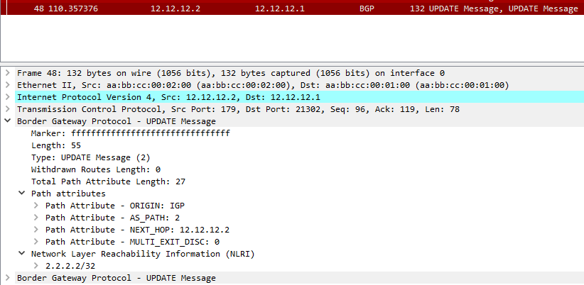


As you can see here, the NLRI is being advertised in the update message and it has Router2 loopback prefix (2.2.2.2/32) as it is being sent to Router1.


I hope this was useful for you!


Samer R. Saleem.


First Image Source: Cisco.com


Saturday, June 26, 2021

Time Based Access Control List on Cisco Router/EIGRP

 In today's post, we will work on creating an Access Control List that works in specific time that we decide, this could be useful for a cases that you want to filter traffic according to that time you set 


In many cases you can use this time based ACL, so let's create a simple lab showing the use of it.


First, as usual we will use a simple topology because there is no need to make thing complicated, all you need is three routers or layer3 switches


In my lab, I will be using three Cisco Routers with 15.4T IOS version.


 Topology below:


 In the topology above, R1 hosts 9, 10, 11 will be advertised as a loopback prefixes from R1.


we will filter the access for these hosts inbound to Site-B  on R3 to stop unwanted traffic after working hours to SVR5, SVR6, SVR7


 in my example, I will filter only one of the IP's for the sake of explanation to make sure the rest of hosts have reachability after the filtration.


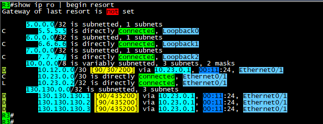
After configuring EIGRP between the three sites, we can see the routing tables with prefixes for the advertised networks

on both sides.


 As you can see above, the host that we will filter is 130.130.130.3/32, we will configure any time that we like the policy 

to start working in it, then we will monitor our logs.


remember it is better to enable logs with the Access list that we will configure in order to see the hits on the policy for the matching

packets.


 Note: the Time based ACL will only be in extended Access Control lists and not in standard.


Now, it is time to define the time range that will be used in access list.


 Commands are:


time-range AFTER-WORK
 absolute start 08:25 26 June 2021

 absolute end 08:43 26 june 2021


the Access list configured as below:

 #ip access-list extended TIME
 #deny   ip host 130.130.130.3 any time-range AFTER-WORK log
 #permit ip any any time-range TIME log


apply it inboung on E0/1 or Router3 and check if its active:


here you go, we have hits on both lines, where we generated some ICMP packets sourced from 130.130.130.3/32

and the permitted log matches the other traffic which include EIGRP packets as well.


As you can see, the packets not reaching the 5.5.5.5/32 SVR when the source of the ICMP is 130.130.130.3/32


 Here above you can see the logs generated by the hit on R3 for both the denied logs and permitted EIGRP packets.

Note: before the time range is activated, it should be seen as inactive as below:


Ok, please note that you must put end option to the time-range settings:


 #time-range AFTER-WORK
 #absolute end 08:42 26 June 2021


 which will put the ACL back to inactive state.


Ok, what about making this task automated? the answer is also by using time-range but with another option which is:


That was it, I hope you enjoyed this post!


Samer Rafid Saleem


Sunday, June 13, 2021

MPLS L3VPN between two Sites that use same Autonomous number

Let's assume that your company asked you to create an MPLS VPN for a customer that wanted to connect two branches of the company together.

However, the customer is using same BGP AS number on both sites, and they can't change it for some reason.

You are required to solve this issue by providing the connectivity and solve any misconfiguration.

In this post, we will discuss what how to configure MPLS-L3VPN type.

Terms will be used:

P => Provider router

PE => provider edge router

CE => Customer edge router

IP addresses are as in the topology.

Using the following topology:

The design shows the ISP network represented by three Routers some of which are P routers (R5) and some are PE's (R2, R3)

On the other hand we will be two sides of the topology to represent CE's Routers.

ISP will be AS#253, while Customer AS#65000

ISP will use OSPF and it's only (area0) you can do the same with any other IGP but of course IS-IS protocol and OSPF are the best due to obvious reasons.

OSPF configuration is enabled on the following interfaces:

R5 E0/0, E0/1, Loopback0

R2 E0/0, Loopback0

R3 E0/1, Loopback0

MPLS LDP is enabled on the same interfaces except the loopbacks.

Command to enable MPLS:

1. option is to enable under interface with command #MPLS IP

2. option is to enable under OSPF process using #MPLS LDP AUTOCONFIG

How to display MPLS FIB table?

R5#show mpls forwarding-table
Local      Outgoing   Prefix           Bytes Label   Outgoing   Next Hop    
Label      Label      or Tunnel Id     Switched      interface              
16         Pop Label  2.2.2.2/32       176893        Et0/0      10.25.0.2   
17         Pop Label  3.3.3.3/32       178410        Et0/1      10.35.0.3   
R5#


Ok, now it's time to configure BGP VPNv4 between the two PE's (R2,R3) which will be the tunnel that we create between the two routers as can be seen in the topology.

we will form the peering using the loopback interfaces.

R2:


 R3:


Next, we will use VRF on the PE's interfaces to CE's, and we will configure the VRF on R2, R3 Route distinguisher RD 65000:65000

Route Target to export and import (65000:65000).


We will need to add interfaces under these VRF's and configure IP addresses on the interfaces facing the CE's routers.

Now, we will enable eBGP between the PE's and the CE's


from the CE's side, it will be normal eBGP configuration, but we will also advertise the loopback's of the CE in BGP table so we can use for testing later on.

the only exceptional thing on CE's we will add the (AllowAS-IN) option on BGP in order to allow incoming BGP AS 65000 updates into each of the routers which should be blocked by default on BGP as a loop prevention mechanism.

of course we have another option to be done on ISP side which is (AS-override), but this time we will use (Allow-AS-IN)

R4, R5 will use same configs:


Now, let's start verifying configs and routes exchange between the two CE's:


As you can see on the output of #show ip bgp that R1 is advertising it's Loopback interface 1.1.1.1/32 and it also receiving the Loopback of R4 4.4.4.4/32

Note the AS path or R1 to reach 4.4.4.4/32 (253, 65000) and this is because R1 allowed same AS to be injected into it's BGP.

 Ok, now let's do some trace between the two Loopbacks:


Success!

you can download the EVE lab file here


Hope this was useful!


Samer R. Saleem.


Thursday, June 2, 2016

EBGP peering - Simple Topology

EBGP peering Lab

The Topology above shows a simple EBGP peers, part of my study journey towards CCIE Routing and Switching certificate.
no matter how big your topology is, EBGP peering basically work the same way

Router #1 contains the configs below:
where the loopback interfaces are used as update source, this type of configs will require IGP route to each loopback interface in order for the routers to be able to
* Adding  the Command #ebgp multihop in order to increase the TTL to be more than 1 and also to cancel the connected check option between two BGP neighbors that requires two routers to be in the same subnet [ connected ] in order to be peers.
=======================================================================
Router #1 Configs :

interface Loopback0
 ip address 100.100.100.100 255.255.255.0
!
interface Loopback100
 ip address 50.50.50.1 255.255.255.0
!
interface FastEthernet0/0
 ip address 10.0.0.1 255.255.255.0
 speed 100
 full-duplex
!
interface FastEthernet0/1
 ip address 13.13.13.1 255.255.255.0
 duplex auto
 speed auto
!
router bgp 100
 no synchronization
 bgp log-neighbor-changes
 network 50.50.50.0 mask 255.255.255.0
 neighbor 3.3.3.3 remote-as 90
 neighbor 3.3.3.3 ebgp-multihop 2
 neighbor 3.3.3.3 update-source Loopback0
 neighbor 5.5.5.5 remote-as 200
 neighbor 5.5.5.5 ebgp-multihop 2
 neighbor 5.5.5.5 update-source Loopback0
 no auto-summary
!

ip route 3.3.3.0 255.255.255.0 13.13.13.3
ip route 5.5.5.0 255.255.255.0 10.0.0.2


=====================================================================

Router #2 Configs
!
interface Loopback0
 ip address 5.5.5.5 255.255.255.0
!
interface Loopback20
 ip address 20.20.20.20 255.255.255.0
!
interface FastEthernet0/0
 ip address 10.0.0.2 255.255.255.0
 speed 100
 full-duplex
!
interface FastEthernet0/1
 no ip address
 shutdown
 duplex auto
 speed auto
!
router bgp 200
 no synchronization
 bgp log-neighbor-changes
 network 20.20.20.0 mask 255.255.255.0
 neighbor 100.100.100.100 remote-as 100
 neighbor 100.100.100.100 ebgp-multihop 2
 neighbor 100.100.100.100 update-source Loopback0
 no auto-summary
!

ip route 100.100.100.0 255.255.255.0 10.0.0.1
!

====================================================================


Router #3 Configs

interface Loopback0
 ip address 3.3.3.3 255.255.255.0
interface Loopback90
 ip address 9.9.9.9 255.255.255.0
interface FastEthernet0/0
 no ip address
 shutdown
 duplex auto
 speed auto
interface FastEthernet0/1
 ip address 13.13.13.3 255.255.255.0
 duplex auto
 speed auto
!
router bgp 90
 no synchronization
 bgp log-neighbor-changes
 network 9.9.9.0 mask 255.255.255.0
 neighbor 100.100.100.100 remote-as 100
 neighbor 100.100.100.100 ebgp-multihop 2
 neighbor 100.100.100.100 update-source Loopback0
 no auto-summary
!

ip route 100.100.100.0 255.255.255.0 13.13.13.1


Now let's verify the configurations :


R1#show ip bgp
BGP table version is 4, local router ID is 100.100.100.100
Status codes: s suppressed, d damped, h history, * valid, > best, i - internal,
              r RIB-failure, S Stale
Origin codes: i - IGP, e - EGP, ? - incomplete

   Network          Next Hop            Metric LocPrf Weight Path
*> 9.9.9.0/24       3.3.3.3                  0             0 90 i
*> 20.20.20.0/24    5.5.5.5                  0             0 200 i
*> 50.50.50.0/24    0.0.0.0                  0         32768 i

===========================================================

R1#show ip bgp summary
BGP router identifier 100.100.100.100, local AS number 100
BGP table version is 4, main routing table version 4
3 network entries using 360 bytes of memory
3 path entries using 156 bytes of memory
4/3 BGP path/bestpath attribute entries using 496 bytes of memory
2 BGP AS-PATH entries using 48 bytes of memory
0 BGP route-map cache entries using 0 bytes of memory
0 BGP filter-list cache entries using 0 bytes of memory
Bitfield cache entries: current 1 (at peak 1) using 32 bytes of memory
BGP using 1092 total bytes of memory
BGP activity 3/0 prefixes, 3/0 paths, scan interval 60 secs

Neighbor        V    AS MsgRcvd MsgSent   TblVer  InQ OutQ Up/Down  State/PfxRcd
3.3.3.3              4    90       8      10        4    0    0                           00:04:04           1
5.5.5.5            4    200       8      10        4    0    0                           00:04:07           1

Hope this was useful!

Samer R. Saleem


Automating Network Configurations with Jinja2 and Python: A Step-by-Step Guide

 In this post, I worked on collecting a code that works with Jinja template. the nice thing in working with Jinja is that you can have basel...