Saturday, June 26, 2021

Time Based Access Control List on Cisco Router/EIGRP

 In today's post, we will work on creating an Access Control List that works in specific time that we decide, this could be useful for a cases that you want to filter traffic according to that time you set 


In many cases you can use this time based ACL, so let's create a simple lab showing the use of it.


First, as usual we will use a simple topology because there is no need to make thing complicated, all you need is three routers or layer3 switches


In my lab, I will be using three Cisco Routers with 15.4T IOS version.


 Topology below:


 In the topology above, R1 hosts 9, 10, 11 will be advertised as a loopback prefixes from R1.


we will filter the access for these hosts inbound to Site-B  on R3 to stop unwanted traffic after working hours to SVR5, SVR6, SVR7


 in my example, I will filter only one of the IP's for the sake of explanation to make sure the rest of hosts have reachability after the filtration.


After configuring EIGRP between the three sites, we can see the routing tables with prefixes for the advertised networks

on both sides.


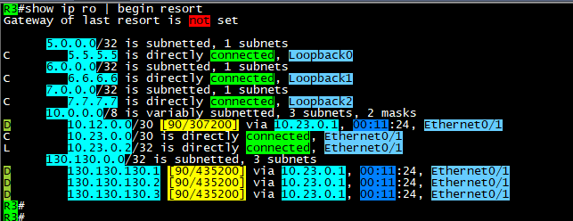
 As you can see above, the host that we will filter is 130.130.130.3/32, we will configure any time that we like the policy 

to start working in it, then we will monitor our logs.


remember it is better to enable logs with the Access list that we will configure in order to see the hits on the policy for the matching

packets.


 Note: the Time based ACL will only be in extended Access Control lists and not in standard.


Now, it is time to define the time range that will be used in access list.


 Commands are:


time-range AFTER-WORK
 absolute start 08:25 26 June 2021

 absolute end 08:43 26 june 2021


the Access list configured as below:

 #ip access-list extended TIME
 #deny   ip host 130.130.130.3 any time-range AFTER-WORK log
 #permit ip any any time-range TIME log


apply it inboung on E0/1 or Router3 and check if its active:


here you go, we have hits on both lines, where we generated some ICMP packets sourced from 130.130.130.3/32

and the permitted log matches the other traffic which include EIGRP packets as well.


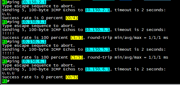
As you can see, the packets not reaching the 5.5.5.5/32 SVR when the source of the ICMP is 130.130.130.3/32


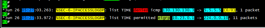
 Here above you can see the logs generated by the hit on R3 for both the denied logs and permitted EIGRP packets.

Note: before the time range is activated, it should be seen as inactive as below:


Ok, please note that you must put end option to the time-range settings:


 #time-range AFTER-WORK
 #absolute end 08:42 26 June 2021


 which will put the ACL back to inactive state.


Ok, what about making this task automated? the answer is also by using time-range but with another option which is:


That was it, I hope you enjoyed this post!


Samer Rafid Saleem


Saturday, June 19, 2021

Filtering even prefixes in third octet with Access Lists

 In this post, we will simulate a filtration scenario where you are tasked to filter (Deny) subnets that has even numbers in the third octet.

we will use the following topology:


Three routers are enough to do the trick, they all working in IGP (OSPF) area 0, each router is using his Loopback0 as OSPF router-id.

all interfaces are enabled for OSPF, we will use R3 to advertise many loopback prefixes

10.150.1.1/32 ==> 10.150.10.1/32

You can of course consider R1 is branch office and R2 is where network security engineer applying filtration to prevent important sites (even 3rd octet subnets) from entering  to both (R2 and R1)

In order to do this, we will create a standard access list, in order to match prefixes and not extended access list.

R2:

#enable

#configure terminal 

#access-list 1 deny   10.150.0.0 0.0.254.255 log
#access-list 1 permit any log

 router ospf 1
 router-id 2.2.2.2
 network 0.0.0.0 255.255.255.255 area 0
 distribute-list 1 in Ethernet0/1
R2#

After we applied the distribute list, we will start getting logs on R2

R2#
*Jun 19 06:11:02.383: %SEC-6-IPACCESSLOGNP: list 1 denied 0 10.150.8.1 -> 0.0.0.0, 1 packet  
*Jun 19 06:11:02.384: %SEC-6-IPACCESSLOGNP: list 1 denied 0 10.150.6.1 -> 0.0.0.0, 1 packet  
*Jun 19 06:11:02.384: %SEC-6-IPACCESSLOGNP: list 1 denied 0 10.150.4.1 -> 0.0.0.0, 1 packet  
*Jun 19 06:11:02.384: %SEC-6-IPACCESSLOGNP: list 1 denied 0 10.150.2.1 -> 0.0.0.0, 1 packet  
*Jun 19 06:11:02.384: %SEC-6-IPACCESSLOGNP: list 1 denied 0 10.150.10.1 -> 0.0.0.0, 1 packet  
R2#


The above logs, shows the even 3rd octet prefixes being denied.

on the same router, you can issue the command: 

#clear ip access-list counters

you will see the permitted prefixes logs:


OK, now let's do a test on R1 to see if we can achieve reachability to the allowed/filtered prefixes:


 As you can see, ping to odd 3rd octet of the subnet 10.150.0.0/16 is allowed and ping is successful, while the even 3rd octet is not successful. and shows the letter (U.U.U) which indicates unreachable flag.

So, how did we do that using this wildcard (0.0.254.255)?

The answer is, since we use 255 to say match any, we mean here match any bit from 0-255

But once we remove the 1st bit, we changed this to match any bit except the 1st bit.

Once we done that, all numbers will be even and odd was excluded from the match process.

So for example: subnet 0 is matched and next subnet which is 1 will not be matched because the 1 bit is set to 0, which means its OFF, then subnet 2 will be matched, but 3 will not because you will not be able to add 2+1 bits because 1 is not enabled to be matched.

then, the access list will decide if you want to deny or allow based on your set option.


I hope this was useful!


Samer R. Saleem


Sunday, June 13, 2021

MPLS L3VPN between two Sites that use same Autonomous number

Let's assume that your company asked you to create an MPLS VPN for a customer that wanted to connect two branches of the company together.

However, the customer is using same BGP AS number on both sites, and they can't change it for some reason.

You are required to solve this issue by providing the connectivity and solve any misconfiguration.

In this post, we will discuss what how to configure MPLS-L3VPN type.

Terms will be used:

P => Provider router

PE => provider edge router

CE => Customer edge router

IP addresses are as in the topology.

Using the following topology:

The design shows the ISP network represented by three Routers some of which are P routers (R5) and some are PE's (R2, R3)

On the other hand we will be two sides of the topology to represent CE's Routers.

ISP will be AS#253, while Customer AS#65000

ISP will use OSPF and it's only (area0) you can do the same with any other IGP but of course IS-IS protocol and OSPF are the best due to obvious reasons.

OSPF configuration is enabled on the following interfaces:

R5 E0/0, E0/1, Loopback0

R2 E0/0, Loopback0

R3 E0/1, Loopback0

MPLS LDP is enabled on the same interfaces except the loopbacks.

Command to enable MPLS:

1. option is to enable under interface with command #MPLS IP

2. option is to enable under OSPF process using #MPLS LDP AUTOCONFIG

How to display MPLS FIB table?

R5#show mpls forwarding-table
Local      Outgoing   Prefix           Bytes Label   Outgoing   Next Hop    
Label      Label      or Tunnel Id     Switched      interface              
16         Pop Label  2.2.2.2/32       176893        Et0/0      10.25.0.2   
17         Pop Label  3.3.3.3/32       178410        Et0/1      10.35.0.3   
R5#


Ok, now it's time to configure BGP VPNv4 between the two PE's (R2,R3) which will be the tunnel that we create between the two routers as can be seen in the topology.

we will form the peering using the loopback interfaces.

R2:


 R3:


Next, we will use VRF on the PE's interfaces to CE's, and we will configure the VRF on R2, R3 Route distinguisher RD 65000:65000

Route Target to export and import (65000:65000).


We will need to add interfaces under these VRF's and configure IP addresses on the interfaces facing the CE's routers.

Now, we will enable eBGP between the PE's and the CE's


from the CE's side, it will be normal eBGP configuration, but we will also advertise the loopback's of the CE in BGP table so we can use for testing later on.

the only exceptional thing on CE's we will add the (AllowAS-IN) option on BGP in order to allow incoming BGP AS 65000 updates into each of the routers which should be blocked by default on BGP as a loop prevention mechanism.

of course we have another option to be done on ISP side which is (AS-override), but this time we will use (Allow-AS-IN)

R4, R5 will use same configs:


Now, let's start verifying configs and routes exchange between the two CE's:


As you can see on the output of #show ip bgp that R1 is advertising it's Loopback interface 1.1.1.1/32 and it also receiving the Loopback of R4 4.4.4.4/32

Note the AS path or R1 to reach 4.4.4.4/32 (253, 65000) and this is because R1 allowed same AS to be injected into it's BGP.

 Ok, now let's do some trace between the two Loopbacks:


Success!

you can download the EVE lab file here


Hope this was useful!


Samer R. Saleem.


Thursday, June 10, 2021

Allowing BGP MD5 authentication through Cisco ASA


Author: Samer R Saleem

We have the following scenario where BGP traffic between routers going through an ASA firewall will face a problem if you have an ASA in the middle of two BGP routers trying to peer and they both are using MD5 authentication.

We will create a lab and solve the issue on the firewall by allowing BGP to authenticate and form peering session between the routers, I will be posting in my labbing results and findings during this and the small topology I used EVE-NG community to simulate this case.

The diagram below is self-explanatory, two routers on the sides and an ASA in between, ip addresses are 192.168.1.0/24 on the left and 12.0.0.0/24 on the right side.

AS111 on R1 and AS222 on R2


you will need to configure the ASA interfaces as below:

G0/0 (ip address and nameif) which is as in the diagram above

G0/1 (ip address and nameif)which is as in the diagram above

Then configure both routers interfaces and ping to make sure ASA is reachable.

To provide reachability I will be using  EIGRP and once completed its adjacency process you will see R2 and R1 networks but they will not have reachability between them, so you will need to add ICMP into ASA firewall inspection:

#class inspection_default

#inspect icmp 

After this, you will have reachability between R1 loopback0 to R2 loopback0, here we start configuring eBGP:

R2:

router bgp 222

bgp log-neighbor-changes

network 200.200.200.200 mask 255.255.255.255

neighbor 1.1.1.1 remote-as 111

neighbor 1.1.1.1 password 12345

neighbor 1.1.1.1 disable-connected-check

neighbor 1.1.1.1 update-source Loopback0

R1:

router bgp 111

bgp log-neighbor-changes

network 100.100.100.100 mask 255.255.255.255

neighbor 2.2.2.2 remote-as 222

neighbor 2.2.2.2 password 12345

neighbor 2.2.2.2 disable-connected-check

neighbor 2.2.2.2 update-source Loopback0

Note: I have created two more loopbacks 100 and 200 in both R1 and R2 and advertised over BGP only, and disabled directly connected check on BGP.

You will see the session comes UP and prefixes appear in both BGP RIB tables.

However, once you add password authentication under BGP, you will start seeing the below logs:

R2(config-router)#

*Sep 11 08:54:44.093: %TCP-6-BADAUTH: No MD5 digest from 1.1.1.1(36963) to 2.2.2.2(179) tableid - 0

R2(config-router)#

*Sep 11 08:54:46.098: %TCP-6-BADAUTH: No MD5 digest from 1.1.1.1(36963) to 2.2.2.2(179) tableid - 0

R2(config-router)#

*Sep 11 08:54:50.106: %TCP-6-BADAUTH: No MD5 digest from 1.1.1.1(36963) to 2.2.2.2(179) tableid - 0

And now the BGP session is lost.

Diagnoses and Solution:

the reason for this is that, BGP is uses TCP 179 protocol, which is fine, but once authentication is used with MD5, ASA will strip the authentication which is TCP option 19


And the routers will not see the MD5 coming with connection attempt because it's being filtered by the firewall, so you will need to add the following part on the Cisco ASA:

1.first you need to create an extended ACL to match the traffic between the BGP routers

access-list bgp extended permit tcp host 1.1.1.1 host 2.2.2.2 eq bgp 

access-list bgp extended permit tcp host 2.2.2.2 host 1.1.1.1 eq bgp 

2.create TCP map to allow option 19

tcp-map allow-tcp-19

tcp-options range 19 19 allow

3.use the global policy map to match the class map BGP that we created to match traffic and apply our settings:

policy-map global_policy

class-map BGP 

match access-list bgp

class BGP

set connection random-sequence-number disable

set connection advanced-options allow-tcp-19

After this is done, you will see the bgp session UP again!

Check the logs again:

R2#

*Sep 11 09:14:59.477: %BGP-5-NBR_RESET: Neighbor 1.1.1.1 active reset (BGP Notification sent)

*Sep 11 09:14:59.477: %BGP-5-ADJCHANGE: neighbor 1.1.1.1 Up 

R2#

RFC about Protection of BGP Sessions via the TCP MD5 Signature Option

https://www.ietf.org/rfc/rfc2385.txt

To download the lab go to my post on Cisco learning Network you will find as a zip attached:

EVE-FILE


I hope this was useful!

Samer R. Saleem


Monday, June 7, 2021

Change Global Protect portal logo

 It is nice and good idea to replace the Global Protect logo to your company logo.

to be more professional and to give better impression about your company attention to details.


in this post, I will be showing you how to do that:

First of all you need to have global protect portal (web based VPN page) enabled.

go to : Network > Global Protect > Portals > General

As you can see  > you should have the interface (outside) and it's IP address 

under appearance: Portal Login Page is set to customized-page.html


Note, in your case you would not see the custom page in the drop list because you did not create it yet.

here is how to create this page:

Go to Device > Response pages >

you will find a list of pages used in your firewall, find and click on Global Protect Portal Login Page

then, select the "Default" and export as shown in the image below:


Once you downloaded it, you can open the ".html" page that you downloaded and edit with texteditor

as you can see below:

change the image source to a different source than the original one, in my case I'm recalling it from the link of a server lab, you can see the highlighted link below:


 once you finished editing this page, save it as (NAME.html)

Go again to Response Pages and select Global Protect portal login page:


Now you can go to the first step and select the new customized page from the drop list and commit your configs.

Hope this was useful!

Samer R. Saleem

Saturday, June 5, 2021

NATing same IP public address for different service (port forwarding)-Destination NAT

05/06/2021

Author: Samer R. Saleem

Subject: NATing per service (port forwarding)


As you might see on another posts, Network requirements change from time to time, which will impose new changes each time.

One of the new scenarios that came into my table was allowing a remote sever to access three finger print devices that works with UDP service.


Of course, I need to make use of my public IP and not waste IP addresses, and sure, the obvious solution for this requirement would be the Network Address translation (NAT).


The following diagram represents the idea of the connection:


 So, our target is to translate the incoming connection according to the requested service:

or example:

if the connection was for the IP: X.X.X.X with UDP port 5500, the Firewall will translate the connection destination to 10.10.180.11


if the connection was for the IP: X.X.X.X with UDP port 5501, the Firewall will translate the connection destination to 10.10.180.12


Finally, if the connection was for the IP: X.X.X.X with UDP port 5502, the Firewall will translate the connection destination to 10.10.180.13


Login to firewall user interface
go to policies > NAT > add

to add a rule with the name of finger print device do the following:
source zone outside destination outside  (the first outside is the internet, the second one is Interface outside of the firewall)
destination IP is X.X.X.X  (which is a real public IP address that you will use to make port forwarding)
service must be (5500, 5501, 5502) 
>>> (if not defined, you can define under objects tab). 

screenshot on how to do that:


here is how to configure and will use the first finger print device in my examples:

Source is outside > destination outside with port > 5500

destination address is the PUBLIC IP (X.X.X.X)

now, go to next tab (Translated Packet), which will take action after the packets translated and will redirect the traffic to internal IP address of the Finger print device1

fill the details as below, and then press OK


 once you done this for device1 you can repeat the process for the other devices.


then allow security access rule
go to security policy
add a new rule
source zone outside, address any to inside zone destination is 95.159.105.100 service ports are 5500,5501,5502 > action is allow


then commit configs


Hope this was useful!


Samer R. Saleem


Python-Jinja template configuration generator for Cisco devices and printout configs to external text files

 In this post, I worked on collecting a code that works with Jinja template. the nice thing in working with Jinja is that you can have basel...