Cisco ASA Firepower
installation process is little bit complicated and require multiple steps in
order to do
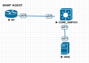
First please check
the simple topology:
Part 1 installing
FMC [FireSight Management Center] vm
You can download the
.OVf file from Cisco.com and install it by using Esxi Vsphere tool to import
the file which is linux based
The following is
used for installation process on the esxi
- Open vsphere client
- Go to file > deploy OVF
template
- Browse the .ovf file on your
computer
- Click next
- Choose think provisioned as a
size on disk
- Choose the name of the VM for
example [FireSight VM]
- Choose the data store on your
host
- Select the network mapping
- Finish then power it on
Note: there is no
need to allocate resources because the vm is already have the resources
allocated.
Installation
Process:
- After powering on the vm wait
for the counter to finish
- After the machine starts you
can login to it using admin as username and password is Admin123
- To login into root you need
to use command sudo su - and the
password is Admin123
- You need to add IP address
for the FMC and you must be on Root user to be able to change settings
- After you login as
"root" type the command #configure-network then you will have
auto-config questions
- IPv4 configs
- Subnet mask
- Gateway
The Network settings
will be updated.
NOTE: you need to
enable the IP address of FMC to reach internet, so you need to add the IP on
the firewall
and also create route under static routing
After everything is
done you can use the following command on your browser to login to FMC
https://172.16.14.50
for example.
NOTE: Management
Interface will need to be shutdown and ip removed from it.
Part two Cisco
Firepower image+ package upload to firewall and installation
You will need the
following in order to accomplish this:
- IOS version stable and
recommended by cisco I used IOS 9.6.3.1 which was recommended by Cisco
- ASASFR boot image which is
".img"
- ASASFR system package which
is ".pkg"
- FTP server which will be used
to upload both .img and .pkg to the Firewall and SFR
- TFTP server which will be used to upload Cisco IOS
for ASA Firewall
Start installation
of Cisco Firepower .img File:
- Locate the image when you
upload into Disk0:/ on the Firewall and of course you must have
- SSD
installed on the Firewall
- Copy the correct full name of
the image for example "asasfr-5500x-boot-6.2.0-2.img"
Before you start
installing the SFR make sure to do the following:
- Shutdown IPS module and
uninstall it.
- Shutdown CXSC module and
uninstall it
- Shutdown SFR module and
uninstall it
This can be done
using the commands:
#sw-module module
ips shutdown
#sw-module module
ips uninstall
#sw-module module
CXSC shutdown
#sw-module module
CXSC uninstall
And same for SFR
module
Make sure that they
are down by using the command #show sw-module and see if they are
"DOWN"
After this process
you will need to start installing the Boot Image that you already uploaded to
the Firewall Disk0:/
We will use the
following commands to install it:
#sw-module module sfr recover
configure image disk0:/asasfr-5500x-boot-6.2.0-2.img
#sw-module module sfr recover
boot [you can enable debugging to
follow up the process during the
boot process #debug module-boot
NOTE: in here you will need
to wait for the process for 15 minutes so don’t rush it!!!!
Now after the
installation finishes you will need to login to the SFR in order to upload the
package file to it
using FTP so first we will need to have IP address on the
SFR
In order to upload
the Package file to it
Lets setup these IP
information:
#session sfr
console [note if the installation wasn’t
finished then you won't be able to do this command]
Use the username
admin and password Admin123 to login to the SFR console
Now start configure
it #ASASFR-BOOT> setup
You will now be
prompted to add information for IPv4, IPv6, NTP, DNS, Domain …etc. then you
will be
asked if you want to apply it n/y??
After you finished
the setup part, you will have ip address reachable in order to transfer the
package to
the Boot Image and install it
Use FTP tool like
FileZilla for the transfer, locate the package file on it and create username
and password
that will be used to access your FTP server and get the file
The FTP process will
take some time because the package size is big.
After upload finish
the SFR will start to extract.
You will be asked if
you want to upgrade then just say "Y" and press enter.
NOTE: this process
will take up to 15 minutes so don’t rush it!!!!!
After this finishes
and if everything is ok you should see the result by using
#show module [it should be up]
FMC-ASA# show module
sfr
----
------------------------------ ---------------- --------------------------
sfr ASA FirePOWER Up 6.2.0-362
Mod Status Data Plane Status Compatibility
----
------------------ --------------------- -------------
sfr Up Up
#show failover [you must see the SFR card in here and in
UP/UP state]
Last Failover at:
18:16:40 AST Jul 6 2017
This host: Primary - Active
Active time: 241396 (sec)
slot 0: ASA5512 hw/sw rev
(1.0/9.6(3)1) status (Up Sys)
Interface Outside (X.X.X.X):
Normal (Monitored)
Interface Inside
(10.211.250.253): Normal (Monitored)
Interface DMZ
(172.16.16.253): Normal (Monitored)
slot 1: SFR5512 hw/sw rev
(N/A/6.2.0-362) status (Up/Up)
ASA FirePOWER, 6.2.0-362, Up, (Not-Monitored)
Other host: Secondary - Standby Ready
Active time: 402 (sec)
slot 0: ASA5512 hw/sw rev
(1.0/9.6(3)1) status (Up Sys)
Interface Outside (X.X.X.X):
Normal (Monitored)
Interface Inside
(10.211.250.252): Normal (Monitored)
Interface DMZ
(172.16.16.252): Normal (Monitored)
slot 1: SFR5512 hw/sw rev
(N/A/6.2.0-362) status (Up/Up)
ASA FirePOWER, 6.2.0-362, Up, (Not-Monitored)
NOTE: you might face
some problem if you have the SFR installed on Different slot on active from the
one on
standby so you must use this command on the active
#no monitor-interface service-module [this is very important because it can cause
the
standby ASA to become active at the same time and
cause
connection problem]
Ok, after the SFR
Card becomes UP you can start configuring it
#session sfr [username admin and password Admin123]
Now setup IP
addresses for the SFR itself [note the previous IP addresses were for the Boot
Image not for the SFR system]
These IP's will be
used to connect the SourceFire "firepower" to Firesight.
Now, Let's connect
the Cisco Firepower to Cisco FireSight
- Connect to SSH on the IP
address of the SFR module "172.16.14.51"
- Input the username admin and
password is Admin123 "default"
- Add the command system>
configure manager add 172.16.14.50 cisco1234
- (where 172.16.14.50 is the Firesight
server, and cisco1234 is shared key between two systems)
- Go to 172.16.14.50
(firesight) and then go to >Devices >device management> add
device
- Full the information for the
Firepower and then click on register
At the same time you
can use Firepower command line to check if the registration was completed
system> show managers and see if the status is complete or still pending.
Hope this was useful!
Samer R. Saleem