Sunday, October 14, 2018

Blocking Mobile Application with Firepower

Blocking Mobile application on Firepower helps in prevent some of the applications that could be risky or has a low business relativity in some companies, today we are going to create rules on Cisco Firepower that helps blocking "snapchat" as an example

First, there are two ways to block application

1. blocking with rule that uses Objects
2. blocking the application with rule directly

Blocking with Objects:

1. Create the applications filter under Objects
Objects > Application Filters > Add Application Filter


add a name for the application filter, then search for the application you want to add and filter in rule, we will search for snapchat application as you can see from the picture above, add to Rule then save.

2. Adding the Application filter to be blocked by Firepower policy
Policies > Access Control > select the Policy to edit ( in my case it's FMC_Access_policy)


3. add a rule > add a name for the rule (SNAPCHAT-FILTER) tick the enable option, change the action to Block, Go to Applications Tab and search for the object we created earlier (APP-FILTER) which has SNAPCHAT application inside then Click Add to Rule, then Add.

 4. Finally save the new rule from the save option on the right upper side of the page, then click on Deploy, tick the devices you want to apply the rule on and click deploy.


After finishing deployment, you can check your rule by going to > Analysis > Connections>Connection events

Note: you will need to enable logging in the rule in order to see it in the events.


Method two, blocking directly:


This is little bit easier to create, first you need to go and create a rule, go to Policies > Access Control > edit policy > add rule

inside the rule, you just need to name the rule, change the action and choose snapchat from the applications list, then enable logging, and add then save and deploy, check below picture, and also to view your rule working or not, go to Analysis > Connections > Connection Events


Good Luck

Saturday, October 13, 2018

SNMPv3-understanding and implementation


SNMPv3 doesn't user community-strings like SNMPv1 and SNMPv2

SNMPv3 can you authentication (MD5 and SHA) and encryption with ( AES and 3DES)

in addition to authentication and encryption, SNMPv3 has a message integrity which ensures the packet has not been changed during transit.


SNMPv3 security levels:

1. noAuthNoPriv  Only username required, no password and no encryption is done.
2. AuthNoPriv MD5 or SHA is used and no encryption
3.AuthPriv in here MD5 and SHA used for authentication plus encryption.


Configuring SNMPv3:

To configure SNMPv3 we need the following

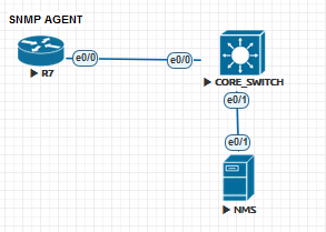
1. SNMP agent which is a Router or Switch (devices we need to connect to SNMP manager)
2. SNMP manager which is the (NMS)

we will configure the SNMP agents:

#snmp-server group CCIE v3 priv

this group will be configured with security model

Now we create the user for this group

#snmp-server user ADMIN CCIE v3 auth MD5 cisco priv AES 128 KEY123


Verify:

Router#show snmp user

User name: ADMIN
Engine ID: 800000090300AABBCC007000
storage-type: nonvolatile        active
Authentication Protocol: MD5
Privacy Protocol: AES128
Group-name: CCIE


#show snmp group
groupname: CCIE                             security model:v3 priv
contextname: <no context specified>         storage-type: nonvolatile
readview : v1default                        writeview: <no writeview specified>
notifyview: <no notifyview specified>
row status: active


Now we have finished configuring the (snmp agent) we will configure the NMS to add the router

all you need to do is add new device, specify the name, choose the snmp version 3 and add the authentication method and user and password and add.


Tuesday, October 9, 2018

BGP Backdoor

BGP backdoor is a way to prefer a higher administrative distance protocol over eBGP for a specific prefix.
for example blow layout:

we have eBGP connection with (R1-R3) but it's with serial link which has a lower bandwidth than our EIGRP link with (R1-R5) from a network performance point of view, we would need to use the higher bandwidth link, and keep low speed link as backup, since we have eBGP we can do that using (BGP backdoor) feature, which would allow router to install a higher administrative distance protocol in the RIB for the same prefix instead of eBGP which is (20)

in each router we have internal link to core switch which will be (192.168.X.X) where X is the router name.

let's configure it:

First step we will configure normal BGP and EIGRP, and we will advertise INTERNAL lan on R3 under both BGP and EIGRP, and we will see R1 is using the route coming via eBGP
R1#show ip route bgp | b Gate
Gateway of last resort is not set

B     192.168.3.0/24 [20/0] via 13.0.0.3, 00:00:28
R1#


R1#show ip cef 192.168.3.0
192.168.3.0/24
  nexthop 13.0.0.3 Serial1/1


Now let's configure BGP Backdoor feature on R1 in order to use the better performance link
R1:
#router bgp 1
#network 192.168.3.0 mask 255.255.255.0 backdoor

showing IP BGP table you will notice (r>) which indicates RIB failure due to Higher administrative distance

R1#show ip bgp | be RPK
RPKI validation codes: V valid, I invalid, N Not found

     Network          Next Hop            Metric LocPrf Weight Path
 *>  192.168.1.0      0.0.0.0                  0         32768 ?
 r>  192.168.3.0      13.0.0.3                 0             0 3 i

R1#show ip bgp rib-failure
  Network            Next Hop                      RIB-failure   RIB-NH Matches
192.168.3.0        13.0.0.3               Higher admin distance              n/a
R1#


Now checking the routing table (RIB) which will show the installed routes that will be used to reach prefixes.

R1#show ip route eigrp  | be Ga
Gateway of last resort is not set

      35.0.0.0/24 is subnetted, 1 subnets
D        35.0.0.0 [90/307200] via 15.0.0.5, 00:07:27, Ethernet0/0
D     192.168.3.0/24 [90/435200] via 15.0.0.5, 00:00:26, Ethernet0/0
D     192.168.5.0/24 [90/409600] via 15.0.0.5, 00:08:07, Ethernet0/0
R1#
Now (R1) is using EIGRP with AD of (90) path instead of (eBGP).

Final check:

R1#traceroute 192.168.3.3 num
Type escape sequence to abort.
Tracing the route to 192.168.3.3
VRF info: (vrf in name/id, vrf out name/id)
  1 15.0.0.5 1 msec 0 msec 1 msec
  2 35.0.0.3 1 msec *  2 msec
R1#


I hope this is useful.


Friday, October 5, 2018

Serial Links bundling with MLPPP

Since a serial link have limitation when it comes to bandwidth, bundling multiple serial links into one link would be a good solution, so having a simple topology like the one below, we will configure a feature that allows us to combine serial links into one, here we have S1/0-3 between R1 which is the Server Router that we can consider as ISP and R2 which is the client router that will get IP address from R1

R1:
starting with creating a virtual interface that will have the IP address configured on it
# interface Multilink1
#ip address 12.0.0.1 255.255.255.0
# peer default ip address pool R1-IP
# ppp multilink
# ppp multilink group 1  

enabling ppp multilink and configuring group1 that we will associate the serial interfaces to it later

the IP address of the Client will be acquired from R1 and that is by using the command
#peer default ip address pool POOL-NAME
and # ip local pool R1-IP 12.0.0.12

now we have created the virtual multilink interface, yet the interface is not up/up, so its time to add interfaces into this multilink.

#interface Serial1/0-3
 #no ip address
 #encapsulation ppp
 #ppp multilink
 #ppp multilink group 1

on Client side we will configure the multilink same as in R1 but we will rely on DHCP to get ip address from R1 and that is done by using #ip address negotiable 
#interface Multilink1
 #ip address negotiated
 #ppp multilink
 #ppp multilink group 1


eventually the Multilink interface will become UP/UP state
time for some verifications:

R2-CLIENT#show ppp all
Interface/ID OPEN+ Nego* Fail-     Stage    Peer Address    Peer Name
------------ --------------------- -------- --------------- --------------------
Mu1          IPCP+ CDPCP+          LocalT   12.0.0.1                       
Se1/0        LCP+                  LocalT   12.0.0.1                       
Se1/1        LCP+                  LocalT   12.0.0.1                       
Se1/2        LCP+                  LocalT   12.0.0.1                       
Se1/3        LCP+                  LocalT   12.0.0.1
                       
R2-CLIENT#

R2-CLIENT#show inter multilink 1
Multilink1 is up, line protocol is up
  Hardware is multilink group interface
  Internet address is 12.0.0.12/32
  MTU 1500 bytes, BW 6176 Kbit/sec, DLY 20000 usec,
     reliability 255/255, txload 1/255, rxload 1/255
  Encapsulation PPP, LCP Open, multilink Open

As you can see above, the multilink bandwidth is the total of all links added to the MLPP and now it is 6176Kbps.

while the physical interface will have original BW
R2-CLIENT#show inter s1/0
Serial1/0 is up, line protocol is up
  Hardware is M4T
  MTU 1500 bytes, BW 1544 Kbit/sec, DLY 20000 usec,
     reliability 255/255, txload 1/255, rxload 1/255
  Encapsulation PPP, LCP Open, multilink Open


Hope this was useful!
Samer R. Saleem

Automating Network Configurations with Jinja2 and Python: A Step-by-Step Guide

 In this post, I worked on collecting a code that works with Jinja template. the nice thing in working with Jinja is that you can have basel...